ADT Gateway
The picture below shows the traffic. The messages Nr. 1,3,4,5 are the requests of the Gateway (ID 0x40000F) to the Sensors (IDs 0x400040, 0x400041, 0x400042). And message Nr. 2 and 6 are the replies of Sensor (ID 0x400040) with the Sensor data 0x55.
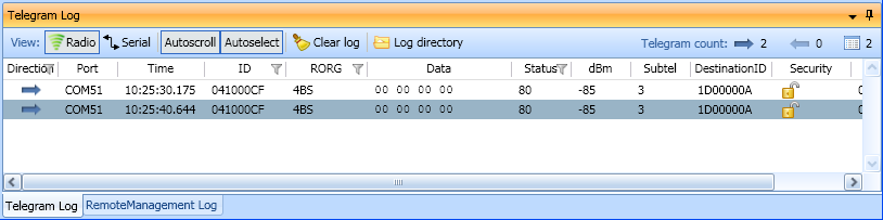
ADT WinEtel showing ADT telegrams
Application file - main.c
#include "EO3100I_API.h"
#include "EO3100I_CFG.h"
#include "string.h"
/************************************************************************-
EVA Board:
EVA300-3
Input PIN:
ADIO_6
for rx UART communication
Outputs PIN:
SCSEDIO0 (CH1 LED)
status of Sensor A (last request successful -> on)
SCLKDIO1 (CH2 LED)
status of Sensor B (last request successful -> on)
WSDADIO02 (CH3 LED)
status of Sensor C (last request successful -> on)
ADIO_7
for tx UART communication
Description:
Demonstrates a gateway which polls for 3 sensor nodes using addressed telegrams.
(ADT).
The gateway uses a list of sensor IDs that is polled every 2 seconds.
For debug purposes the ADT gateway software outputs the received/send telegrams
on the serial interface. This can be used to monitor the communication.
Notes:
Adopt the sensor ID list (u32SensorId[]) to your hardware IDs!
Read the help file Examples/Adt Adress Destination Telegram for more informations!
The sensors that communicate with the gateway must be programmed
with the software in Examples\ADT-AddressDestinationTelegram\ADTSensor
See API FAQ on how to obtain chipIDs.
-************************************************************************/
code uint8 VERSION_APP[] = {0xE0,'V','E','R','S','I','O','N',1,0,1,1,'A','A','D','T','G','A','T','E','W','A','Y',0x00,0xE0};
#define LED_CH3 WSDADIO_2
#define LED_CH2 SCLKDIO_1
#define LED_CH1 SCSEDIO_0
#define RADIO_BUFF_LENGTH 21
void main()
{
const uint32 u32SensorId[3] = { // please enter your sensor IDs here
0x0410007B, // can be obtained with DoplhinProgrammer:
0x04100021, // Module Information tab > Retrieve Module Information
0x04100024,
};
uint8 u8SensorIdx; // Sensor index
PACKET_SERIAL_TYPE packet; // Serial interface packet
TIMER_TYPE myTimer_1; // Scheduler
TEL_RADIO_TYPE2 rTelTx, rTelRx; // ERP2 telegrams
TEL_PARAM_TYPE2 pTelTx, pTelRx; // ERP2 telegrams parameters
uint32 u32MyId; // Gateway ID
uint8 u8packetData[RADIO_BUFF_LENGTH+16]; // Buffer for ESP3 data packet
uint32 *pID;
uint8 u8SrcIdLength;
uint8 u8DstIdLength;
mainInit();
misc_getId(&u32MyId); // get Chip ID
// Header: 32-bit originator ID, 32-bit destination ID. No extended header. RPS type
// Source ID
rTelTx.raw.bytes[1] = 0x00; // ID MSB
rTelTx.raw.bytes[2] = 0x00; // ID
rTelTx.raw.bytes[3] = 0x00; // ID
rTelTx.raw.bytes[4] = 0x00; // ID LSB --> API sends with chip ID
// Destination ID: 4 bytes [5..8] of destination ID are inserted later in the program.
rTelTx.raw.bytes[5] = 0x00;
rTelTx.raw.bytes[6] = 0x00;
rTelTx.raw.bytes[7] = 0x00;
rTelTx.raw.bytes[8] = 0x00;
// Data
rTelTx.raw.bytes[9] = 0x00; // DATA
// Length
rTelTx.raw.u8Length = 11;
pTelTx.p_tx.u8SubTelNum = 3; // transmit 3 subtelegram
packet.u8DataBuffer = &u8packetData[0]; // Serial packet data buffer initialisation.
time_setTimerCount(&myTimer_1, 100); // Set first time value for scheduler
u8SensorIdx = 0;
radio_enableRx(1); // Activate the radio reception
while(1)
{
CLR_WDT();
// Every 2 seconds send an adressed telegram to a sensor to request data
{
time_setTimerCount(&myTimer_1, 2000);
io_setDigital(WSDADIO_2, 0);
io_setDigital(SCLKDIO_1, 0);
io_setDigital(SCSEDIO_0, 0);
memcpy(&rTelTx.raw.bytes[5], (uint8 *)&u32SensorId[u8SensorIdx] , 4);
u8SensorIdx++;
if(u8SensorIdx >= 3)
u8SensorIdx = 0;
}
// If not received telegram go to the start of the while-loop
continue;
// Get the telegram ID
pID = (uint32*)misc_getID2(&rTelRx, &u8SrcIdLength, &u8DstIdLength);
// Telegram received. 1BS telegram, with 32-bit Bit orignator ID and without destination ID?
{
// The Id corresponds to any of the sensors?
if(*pID == u32SensorId[0])
io_setDigital(LED_CH1, 1);
if(*pID == u32SensorId[1])
io_setDigital(LED_CH2, 1);
if(*pID == u32SensorId[2])
io_setDigital(LED_CH3, 1);
}
// Convert ERP2 radio telegram to ESP3 packet and send it over UART
{
}
}
}
Config file - EO3100I_CFG.h
// Generated on 2013-06-07 13:03:43 by DolphinAPIConfigurator 1.1.0.20
#ifndef _EO3100I_CFG_H_INCLUDED
#define _EO3100I_CFG_H_INCLUDED
void startupInit();
void mainInit();
//*********************UART PARAM***************************
#define RX_RING_SIZE 34
#define TX_RING_SIZE 34
extern volatile uint8 xdata u8RxRing[RX_RING_SIZE];
extern volatile uint8 xdata u8TxRing[TX_RING_SIZE];
extern uint8 uart_param[];
//*********************RADIO PARAM***************************
#define RADIO_BUFF_NUM 10
#define RADIO_MATURITY_TIME 100
//*********************FILTER PARAM***************************
#define FILTER_NUM 1
extern volatile uint32 xdata u32gFilterValue[FILTER_NUM];
extern volatile uint8 xdata u8gFilterCfg[FILTER_NUM];
//*********************IO PARAM******************************
extern uint8 code io_param[];
#endif //_EO3100I_CFG_H_INCLUDED
Config file - EO3100I_CFG.c
// Generated on 2013-06-07 13:04:21 by DolphinAPIConfigurator 1.1.0.20
#include "EO3100I_API.h"
#include "EO3100I_CFG.h"
//*********************API INIT***************************
//Note: Function is called from startup.a51. Global variables are not yet initialized!
void startupInit()
{
io_init(io_param);
}
void mainInit()
{
radio_init(RADIO_BUFF_NUM, RADIO_MATURITY_TIME);
UART_INIT(uart_param, SET_ALL_PARAM);
misc_init();
}
//*********************UART PARAM***************************
volatile uint8 xdata u8RxRing[RX_RING_SIZE];
volatile uint8 xdata u8TxRing[TX_RING_SIZE];
uint8 uart_param[] = {
BAUD_57600, //IDX_BAUD
RX_RING_SIZE, //IDX_RX_RING_SIZE
TX_RING_SIZE, //IDX_TX_RING_SIZE
};
//*********************RADIO PARAM***************************
volatile RADIO_BUFFER_TYPE xdata gRadioBuff[RADIO_BUFF_NUM];
//*********************FILTER PARAM***************************
volatile uint32 xdata u32gFilterValue[FILTER_NUM];
volatile uint8 xdata u8gFilterCfg[FILTER_NUM];
//*********************IO PARAM******************************
uint8 code io_param[] = {
0x07, //IDX_GPIO_CONF
0x00, //IDX_GPIO0_CONF
0x00, //IDX_GPIO0_PULL_CONF
0x07, //IDX_GPIO0_DIR
0x00, //IDX_GPIO1_AN
0x00, //IDX_GPIO1_CONF0
0xC0, //IDX_GPIO1_CONF1
0x03, //IDX_GPIO1_DIG_CONF
0x80, //IDX_GPIO1_DIR
0x7F, //IDX_GPIO1_PULL
0x0C, //IDX_GPIO2_CONF
0x00, //IDX_GPIO2_DIR
0x00, //IDX_GPIO0
0x00, //IDX_GPIO1
0x00, //IDX_GPIO2
};
// I/O Configuration overview
//
// Pin : Interface Direction Pull InitValue Interrupt
// SCSEDIO0 : Digital I/O Out None 0 No
// SCLKDIO1 : Digital I/O Out None 0 No
// WSDADIO2 : Digital I/O Out None 0 No
// RSDADIO3 : Digital I/O In None 0 No
// ADIO0 : Digital I/O In Up 0 No
// ADIO1 : Digital I/O In Up 0 No
// ADIO2 : Digital I/O In Up 0 No
// ADIO3 : Digital I/O In Up 0 No
// ADIO4 : Digital I/O In Up 0 No
// ADIO5 : Digital I/O In Up 0 No
// ADIO6 : UART In Up 0 No
// ADIO7 : UART Out None 0 No
// WXIDIO : Digital I/O In Up 0 No
// WXODIO : Digital I/O In Up 0 No
// WAKE0 : Digital I/O In None 0 No
// WAKE1 : Digital I/O In None 0 No