Macros |
| #define | io_measSingleRVDD(u8Pin, u8Res, pu16Value) io_measAnalog(RVDD, RVSS, u8Pin, RVSS, u8Res, pu16Value) |
| #define | io_measSingleVBG(u8Ref, u8Pin, u8Res, pu16Value) io_measAnalog(u8Ref, RVSS, u8Pin, RVSS, u8Res, pu16Value) |
| #define | io_measSingleEXT(u8ExtRef, u8Pin, u8Res, pu16Value) io_measAnalog(u8ExtRef, RVSS, u8Pin, RVSS, u8Res, pu16Value) |
Functions |
| void | io_init (uint8 *pu8Param) |
| void | io_setDigital (PIN_TYPE u8Pin, uint8 u8Value) |
| void | io_setPort (PORT_TYPE u8Pin, uint8 u8Value) |
| void | io_getDigital (PIN_TYPE u8Pin, uint8 *pu8Value) |
| void | io_getPort (PORT_TYPE u8Pin, uint8 *pu8Value) |
| void | io_togDigital (PIN_TYPE u8Pin) |
| RETURN_TYPE | io_setAnalog (ANSRC_TYPE u8Pin, ANSRC_TYPE u8Src, uint8 u8On) |
| void | io_setDAC (uint8 u8Value, uint8 u8On) |
| void | io_enableAnalog (uint8 u8Enable) |
| RETURN_TYPE | io_measAnalog (ANSRC_TYPE u8RefPos, ANSRC_TYPE u8RefNeg, ANSRC_TYPE u8MeasPos, ANSRC_TYPE u8MeasNeg, uint8 u8Res, uint16 *pu16Value) |
| RETURN_TYPE | io_ulpMeasAnalog (ANSRC_TYPE u8MeasPos, ANSRC_TYPE u8MeasNeg, sint16 *ps16Value) |
| void | io_ulpScaleAnalog (sint16 s16Ref, sint16 s16Meas, uint8 u8Res, uint16 *pu16Value) |
| void | io_ADIO02initCB (void code *pu16FnPtr) |
| void | io_ADIO02enableCB (uint8 u8Enable) |
| void | io_ADIO46initCB (void code *pu16FnPtr) |
| void | io_ADIO46enableCB (uint8 u8Enable) |
| void | io_getAnalogRnd (uint8 u8Iterations, uint16 *pu16Rnd) |
| void | io_Wake0initCB (void code *pu16FnPtr) |
| void | io_Wake0enableCB (uint8 u8Enable) |
| void | io_Wake1initCB (void code *pu16FnPtr) |
| void | io_Wake1enableCB (uint8 u8Enable) |
| void | io_i2c_start () |
| void | io_i2c_stop () |
| uint8 | io_i2c_write (uint8 u8Data) |
| uint8 | io_i2c_read (uint8 u8Ack) |
Detailed Description
The IO module is used to access and configure the GPIO pins. The module makes it possible:
- configure GPIO as digital IO
- configure GPIO as analogue IO
- read/write/toggle value on a digital pin
- read/write analogue value on a pin
- use the IO pin as an external interrupt source with the help of a callback function
- configure IO pins for the UART and SPI module
- configure pull up/downs for the digital IO pins
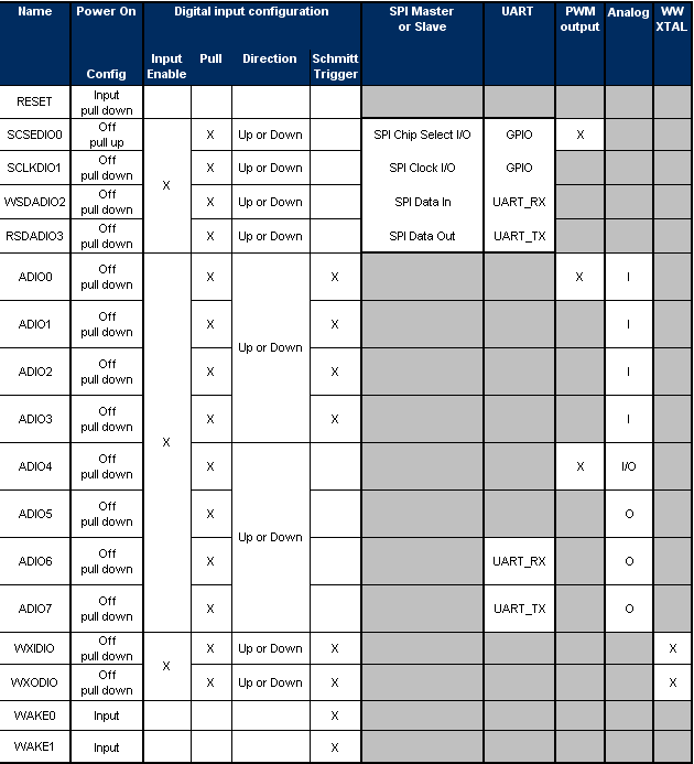
The IO module is configured with the help of Dolphin APIConfigurator. The Dolphin APIConfigurator generates the initialization parameters for the pins in the array io_param[]. These parameters are initiated in the API using the
io_init function. The possible IO initialization for the pins are showed on the picture below.
- Note:
- Be sure to initialise the IO module using Dolphin APIConfigurator correctly otherwise the peripherial sw modules will not work correctly. The Ports WXID_IO,WXOD_IO are low Power with Output 1.8V and Current low.
-
The default level of an output IO pin is LOW. When the io_init function is called all pins which are configured as output are set active and LOW. If the application requires that a pin is set always HIGH, he io_setDigital or io_setPort hast to be called prior mainInit();.
GPIO pins
Macro Definition Documentation
Measures single ended analog value against RVSS. Use RVDD as reference
- Parameters:
-
| [in] | u8Pin | Pin to measure |
| [in] | u8Res | Resolution |
| [out] | *pu16Value | Pointer to Measured value |
- Returns:
- -
| #define io_measSingleVBG |
( |
|
u8Ref, |
|
|
|
u8Pin, |
|
|
|
u8Res, |
|
|
|
pu16Value |
|
) |
| io_measAnalog(u8Ref, RVSS, u8Pin, RVSS, u8Res, pu16Value) |
Measures single ended analog value against RVSS. Uses VBG as reference
- Parameters:
-
| [in] | u8Ref | Pin with VBG reference |
| [in] | u8Pin | Pin to measure |
| [in] | u8Res | Resolution |
| [out] | *pu16Value | Pointer to Measured value |
- Returns:
- -
| #define io_measSingleEXT |
( |
|
u8ExtRef, |
|
|
|
u8Pin, |
|
|
|
u8Res, |
|
|
|
pu16Value |
|
) |
| io_measAnalog(u8ExtRef, RVSS, u8Pin, RVSS, u8Res, pu16Value) |
Measures single ended analog value against external reference.
- Parameters:
-
| [in] | u8Ref | Pin where the external reference is read |
| [in] | u8Pin | Pin to measure |
| [in] | u8Res | Resolution |
| [out] | *pu16Value | Pointer to Measured value |
- Returns:
- -
- Note:
- Be sure to configure 1 pin where the external reference as input is read
Function Documentation
| void io_init |
( |
uint8 * |
pu8Param | ) |
|
Configures the I/O ports and for digital I/O output ports sets the initial value.
- Parameters:
-
| [in] | *pu8Param | Pointer to the list of parameters to configure the I/Os generated by DolphinV4 API Configurator. See #io_param[] |
- Returns:
- -
- See also:
- IO_PARAM_IDX, io_init
| void io_setDigital |
( |
PIN_TYPE |
u8Pin, |
|
|
uint8 |
u8Value |
|
) |
| |
Sets the digital value of a pin
- Parameters:
-
| [in] | u8Pin | I/O pin code. See PIN_TYPE |
| [in] | u8Value | Value to set in the I/O pin, this can be 1 or 0 |
- Returns:
- -
- Note:
- It is allowed to use this function in an interrupt callback function!
- See also:
- io_getDigital, io_togDigital
| void io_setPort |
( |
PORT_TYPE |
u8Pin, |
|
|
uint8 |
u8Value |
|
) |
| |
Sets the digital value of the hole port
- Parameters:
-
| [in] | u8Port | I/O port code. See PORT_TYPE |
| [in] | u8Value | Value to set in the I/O port |
- Returns:
- -
- Note:
- It is allowed to use this function in an interrupt callback function!
- See also:
- io_setPort, io_getPort
| void io_getDigital |
( |
PIN_TYPE |
u8Pin, |
|
|
uint8 * |
pu8Value |
|
) |
| |
Gets the digital value of a pin
- Parameters:
-
| [in] | u8Pin | I/O pin code. See PIN_TYPE |
| [out] | u8Value | Digital value (0 or 1) read from the I/0 pin |
- Returns:
- -
- Note:
- It is allowed to use this function in an interrupt callback function!
- See also:
- io_setDigital, io_togDigital
| void io_getPort |
( |
PORT_TYPE |
u8Pin, |
|
|
uint8 * |
pu8Value |
|
) |
| |
Gets the digital value of the hole port
- See also:
- definition
- Parameters:
-
| [in] | u8Port | I/O port code. See PORT_TYPE |
| [out] | *u8Value | Pointer to a value where the port state is stored |
- Returns:
- -
- Note:
- It is allowed to use this function in a callback function!
- See also:
- io_setPort, io_getPort
Toggles the digital value of an output pin: when pin is '1' writes a '0' and viceversa
- Parameters:
-
- Returns:
- -
- Note:
- It is allowed to use this function in a callback function!
- See also:
- io_getDigital, io_setDigital
Sets the analog source as output.
- Parameters:
-
| [in] | u8Pin | Pin output, can be one of the constants from GPIO1_ADIO4 - GPIO1_ADIO7 or ALL (when u8On == 0) |
| [in] | u8Src | Analog signal source, can be one of the constants RVDD, RVSS, VBG, DAC, VTEMP, VDD_4 |
| [in] | u8On | Switch output 0=Off, 1...255 On |
- Returns:
- OK Pin switched NOT_VALID_PARAM One of the parameters given is not in allowed range
- Note:
- Be sure before using this function to configure this pin as analog output
-
Due to hardware restrictions it is not possible to simultaneously perform analog measurent and analog output.
| void io_setDAC |
( |
uint8 |
u8Value, |
|
|
uint8 |
u8On |
|
) |
| |
Sets the DAC
- Parameters:
-
| [in] | u8Value | Value to set on DAC |
| [in] | u8On | Switch output 0=Off, 1...255 On |
- Returns:
- -
- Note:
- Due to hardware restrictions it is not possible to simultaneously perform analog measurent and analog output.
| void io_enableAnalog |
( |
uint8 |
u8Enable | ) |
|
Radio and analog measurements share the same analog to digital converter. Therefor it is necessary to enable the analog module prior of performing measurements. Whilst analog measurements measurements are enabled it is not possible to perform an radio receiving or transmitting. Therefor special care needs to be taken when and how long the analog measurements are enabled.
- Parameters:
-
| [in] | u8Enable | 0=disable, all others =enable |
- Returns:
- -
- Note:
- Be sure to disable analog measurement when you want to use radio again. Do not call the io_enableAnalog(>0) more than once, before calling io_enableAnalog(0)!!
-
Due to hardware restrictions it is not possible to simultaneously perform analog measurent and analog output.
Measures analog value
- Parameters:
-
| [in] | u8RefPos | Positive reference can be either ANSRC_TYPE or ADIO0 - ADIO7 (see PIN_TYPE) |
| [in] | u8RefNeg | Negative reference can be either ANSRC_TYPE or ADIO0 - ADIO7 (see PIN_TYPE) |
| [in] | u8MeasPos | Positive signal input can be either ANSRC_TYPE or ADIO0 - ADIO7 (see PIN_TYPE) |
| [in] | u8MeasNeg | Negative signal input can be either ANSRC_TYPE or ADIO0 - ADIO7 (see PIN_TYPE) |
| [in] | u8Res | Resolution (1-12 bit) is the range of measurement scaled by reference |
| [out] | *u16Value | Pointer to Measured value |
- Returns:
- OK The measurement was successful NOT_VALID_PARAM One of the parameters given is not in allowed range (u16Value is not modified)
- Note:
- Be sure to wait a certain ammount of time before the signal gets stable
-
As radio components will be used for analog measurement it is necessary to call io_enableAnalog(1) before calling io_measAnalog(...) to switch analog part working. After calling io_measAnalog(...) the function io_enableAnalog(0) has to be called to switch radio components working. If more than one call to io_measAnalog will be done and between that calls radio is not needed, then here io_enableAnalog(0) need only to be called after the last use of io_measAnalog.
#define BIT12 (1<<12)
uint16 value;
float fVolt;
uint8 str[50];
.....
fVolt = 1.8 * value / (BIT12-1);
sprintf(str,"%1.3fV (%d)\n",fVolt,value);
- Note:
- Due to hardware restrictions it is not possible to simultaneously perform analog measurent and analog output.
Measures analogue value for ulp applications
- Parameters:
-
| [in] | u8MeasPos | Positive Input signal to measure, can be either ANSRC_TYPE or ADIO0 - ADIO7 (see PIN_TYPE) |
| [in] | u8MeasNeg | Negative Input signal to measure, can be either ANSRC_TYPE or ADIO0 - ADIO7 (see PIN_TYPE) |
| [out] | *ps16Value | Pointer to Measured value. This is a value measured against an internal 0.9V voltage. |
- Returns:
- OK The measurement was successful NOT_VALID_PARAM One of the parameters given is not in allowed range (u16Value is not modified)
- Note:
- Be sure to wait a certain ammount of time before the signal gets stable
-
As radio components will be used for analog measurement it is necessary to call io_enableAnalog(1) before calling io_ulpMeasAnalog(...) to switch analog part working. After calling io_ulpMeasAnalog(...) the function io_enableAnalog(0) has to be called to switch radio components working. If more than one call to io_measAnalog will be done and between that calls radio is not needed, then here io_enableAnalog(0) need only to be called after the last use of io_ulpMeasAnalog.
-
The returned measurement value is a relative value and cannot be used in the application till it is scaled using io_ulpScaleAnalog. To use the ulp analog measurement it is necessary to make single measurements of the negative and positive reference, and the negative and positive measurement pin.
The following example shows the code for performing three measurements of ADIO_1, ADIO_2 and ADIO_3 against GND. The selected
reference is
RVDD, the resolution of the result is 8 bit, so when the measurement value is 0 then GND is measured, or 0xff the voltage of
RVDD is measured.
sint16 s16ref;
sint16 s16adio1value;
sint16 s16adio2value;
sint16 s16adio3value;
uint16 u16adio1value;
uint16 u16adio2value;
uint16 u16adio3value;
- Note:
- Due to hardware restrictions it is not possible to simultaneously perform analog measurent and analog output.
- See also:
- io_ulpScaleAnalog, io_measAnalog
| void io_ulpScaleAnalog |
( |
sint16 |
s16Ref, |
|
|
sint16 |
s16Meas, |
|
|
uint8 |
u8Res, |
|
|
uint16 * |
pu16Value |
|
) |
| |
Scales the 2 with io_ulpMeasAnalog measured values (reference and measurement) to given resolution
- Parameters:
-
| [in] | s16Ref | Measured reference (output of io_ulpMeasAnalog) |
| [in] | s16Meas | Measured measurement value (output of io_ulpMeasAnalog) |
| [in] | u8Res | Resolution |
| [out] | *pu16Value | Pointer to scaled value |
- Returns:
- -
- Note:
- Example using this function see description of io_ulpMeasAnalog
-
If the signess of the reference and measured value differ 0 is returned.
- See also:
- io_ulpMeasAnalog, io_measAnalog
| void io_ADIO02initCB |
( |
void code * |
pu16FnPtr | ) |
|
Sets function pointer for callback function in interrupt of GPIO1 pins 0, 1 and 2
- Parameters:
-
| [in] | *pu16FnPtr | Pointer to the callback function which will be called when GPIO1 pins 0, 1 or 2 generates an interrupt |
- Returns:
- -
- See also:
- io_ADIO02enableCB, io_ADIO46initCB, io_ADIO46enableCB
| void io_ADIO02enableCB |
( |
uint8 |
u8Enable | ) |
|
Enables or disables callback when GPIO1 pins 0, 1 or 2 generates an interrupt
- Parameters:
-
| [in] | u8Enable | TRUE, callback enabled, FALSE, callback disabled |
- Returns:
- -
- Note:
- Do not stay in the callback function too long (not more than 100 us because that takes too much time away from the schedule)
-
The callback function will be called during an interrupt! Do only use allowed API-Functions in callback function. Do not switch the registerbank. Do not use overlaying and optimizing in callback function. You are allowed to:
- allocate local variables which are only stored in registers
- you are allowed to read from flash using code[]
- you are allowed to change global variables of the code but before be sure to set them to volatile
-
If you did not initialised callback function pointer and you enable callback function, then the interrupt occurs, but function cannot be called and interrupt returns without function. Program will not crash, but resources are used.
void callback()
{
...
}
void yourFunction()
{
.....
.....
.....
}
- See also:
- io_ADIO02initCB, io_ADIO46initCB, io_ADIO46enableCB
| void io_ADIO46initCB |
( |
void code * |
pu16FnPtr | ) |
|
Sets function pointer for callback function in interrupt of GPIO1 pins 4, 5 and 6
- Parameters:
-
| [in] | *pu16FnPtr | Pointer to the callback function which will be called when GPIO1 pins 4, 5 or 6 generates an interrupt |
- Returns:
- -
- See also:
- io_ADIO46enableCB, io_ADIO02initCB, io_ADIO02enableCB
| void io_ADIO46enableCB |
( |
uint8 |
u8Enable | ) |
|
Enables or disables callback when GPIO1 pins 4, 5 or 6 generates an interrupt
- Parameters:
-
| [in] | u8Enable | TRUE, callback enabled, FALSE, callback disabled |
- Returns:
- -
- Note:
- Do not stay in the callback function too long (not more than 100 us because that takes too much time away from the schedule)
-
The callback function will be called during an interrupt! Do only use allowed API-Functions in callback function. Do not switch the registerbank. Do not use overlaying and optimizing in callback function. You are allowed to:
- allocate local variables which are only stored in registers
- you are allowed to read from flash using code[]
- you are allowed to change global variables of the code but before be sure to set them to volatile
-
If you did not initialised callback function pointer and you enable callback function, then the interrupt occurs, but function cannot be called and interrupt returns without function. Program will not crash, but resources are used.
void callback()
{
...
}
void yourFunction()
{
.....
.....
.....
}
- See also:
- io_ADIO46initCB, io_ADIO02initCB, io_ADIO02enableCB
| void io_getAnalogRnd |
( |
uint8 |
u8Iterations, |
|
|
uint16 * |
pu16Rnd |
|
) |
| |
Calculates a random 16 bit value reading the noise of the ADC
- Parameters:
-
| [in] | u8iterations | Number of iterations for calculating values, as higher es better Meaningful minimum value is 4 |
| [out] | *pu16Rnd | Pointer to put the random value back |
- Returns:
- -
- Note:
- The function reads the noise of the ADC. It is necessary to enable the radio receiver (call radio_enableRx(1);) prior calling this function. Otherwise there is no noise and the function will always return 0.
-
As more iterations will be done as more the value will be random and as longer the function will take. A meaningful value is 10. If the parameter is < 4 then 4 will be taken.
- See also:
| void io_Wake0initCB |
( |
void code * |
pu16FnPtr | ) |
|
Sets function pointer for callback function in interrupt of wake 0 pin
- Parameters:
-
| [in] | *pu16FnPtr | Pointer to the callback function which will be called when wake pin 0 changes |
- Returns:
- -
- See also:
- io_Wake0enableCB
| void io_Wake0enableCB |
( |
uint8 |
u8Enable | ) |
|
Enables or disables callback when wake 0 pin changes
- Parameters:
-
| [in] | u8Enable | TRUE, callback enabled, FALSE, callback disabled |
- Returns:
- -
- Note:
- Do not stay in the callback function too long (not more than 100 us because that takes too much time away from the schedule)
-
The callback function will be called during an interrupt! Do only use allowed API-Functions in callback function. Do not switch the registerbank. Do not use overlaying and optimizing in callback function. You are allowed to:
- allocate local variables
- you are allowed to read from flash using code[]
- you are allowed to change global variables of the code but before be sure to set them to volatile
-
If you did not initialised callback function pointer and you enable callback function, then the interrupt occurs, but function cannot be called and interrupt returns without function. Program will not crash, but resources are used.
void callback()
{
uint8 u8state;
if (u8state & 0x04)
{
... staff to do, when wake 0 pin is set
}
...
}
void yourFunction()
{
.....
.....
.....
}
- See also:
- io_Wake0initCB, isr_sysInit
| void io_Wake1initCB |
( |
void code * |
pu16FnPtr | ) |
|
Sets function pointer for callback function in interrupt of wake 1 pin
- Parameters:
-
| [in] | *pu16FnPtr | Pointer to the callback function which will be called when wake pin 1 changes |
- Returns:
- -
- See also:
- io_Wake1enableCB
| void io_Wake1enableCB |
( |
uint8 |
u8Enable | ) |
|
Enables or disables callback when wake 1 pin changes
- Parameters:
-
| [in] | u8Enable | TRUE, callback enabled, FALSE, callback disabled |
- Returns:
- -
- Note:
- Do not stay in the callback function too long (not more than 100 us because that takes too much time away from the schedule)
-
The callback function will be called during an interrupt! Do only use allowed API-Functions in callback function. Do not switch the registerbank. Do not use overlaying and optimizing in callback function. You are allowed to:
- allocate local variables
- you are allowed to read from flash using code[]
- you are allowed to change global variables of the code but before be sure to set them to volatile
-
If you did not initialised callback function pointer and you enable callback function, then the interrupt occurs, but function cannot be called and interrupt returns without function. Program will not crash, but resources are used.
#pragma NOAREG
void callback()
{
uint8 u8state;
if (u8state & 0x08)
{
... staff to do, when wake 1 pin is set
}
...
}
void yourFunction()
{
.....
.....
.....
}
- See also:
- io_Wake0initCB, isr_sysInit
| uint8 io_i2c_write |
( |
uint8 |
u8Data | ) |
|
Writes one byte when using SCSEDIO and SCLKDIO as a SW emulated i2c interface
- Parameters:
-
- Returns:
- I2C_ACK Writing was successful I2C_NACK Writing failed
- Note:
- Use SCLKDIO_1 for SCL and SCSEDIO_0 for SDA. Be sure both pins are configured as input pull up.
- See also:
- io_i2c_start, io_i2c_stop, io_i2c_read, mem_readEEPROM, mem_writeEEPROM
| uint8 io_i2c_read |
( |
uint8 |
u8Ack | ) |
|
Reads one byte when using SCSEDIO and SCLKDIO as a SW emulated i2c interface
- Parameters:
-
| [in] | u8Ack | I2C_ACK or I2C_NACK how to acknowledge the 9th bit |
- Returns:
- u8Data Data read
- Note:
- Use SCLKDIO_1 for SCL and SCSEDIO_0 for SDA. Be sure both pins are configured as input pull up.
- See also:
- io_i2c_start, io_i2c_stop, io_i2c_read, mem_readEEPROM, mem_writeEEPROM