|
Functions | |
| void | spi_init (uint8 *pu8Param) |
| void | spi_setCS (bit1 u1Val) |
| RETURN_TYPE | spi_getSendBuffer (uint8 *u8SendBuff, uint8 *u8GetBuff, uint8 u8NoBytes, SPI_PACKETSIZE u8PacketSize, DPLX_MODES u8Dplx) |
Detailed Description
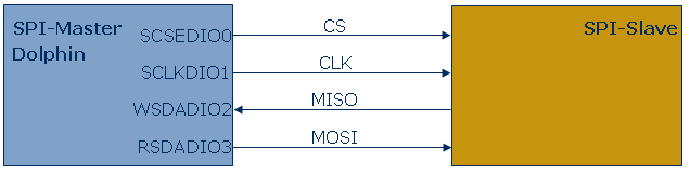
The SPI module is used for communication between the DOLPHIN IC and a HOST using the SPI protocol. The SPI module supports communication where the DOLPHIN acts as SPI-Master and the HOST acts SPI-Slave.
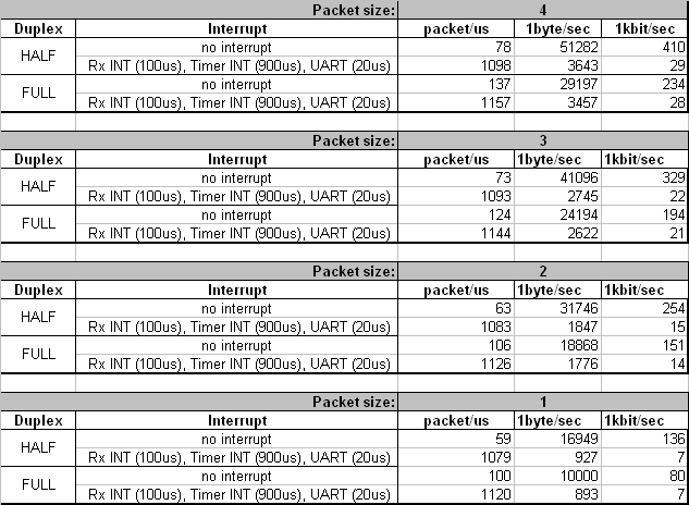
The SPI module supports packet transmission. The size of one packet can be 1,2,3 or 4 bytes. The CS can't be modified during packet transmission. The maximum speed of one packet transmission is 2Mbit. Between two packets a certain processing delay is needed called interpacket delay. size of the interpacket delay depends on the following factors:
- duplex mode (half duplex smaller delay)
- packet size (the bigger packet, the more delay between packets)
- other active interrupts
The initialization of the SPI module is done through Dolphin APIConfigurator. The generated settings are saved to the file EO3100I_CFG.h.
The SPI interfaces uses the following pins:
- SCSEDIO0 - Chip select (CS)
- SCLKDIO1 - SPI clock (CLK)
- WSDADIO2 - Master In Slave Out (MISO)
- RSDADIO3 - Master Out Slave In (MOSI)
There are two possibilities how control CS (configured with spi_init with the parameters).
- manual CS mode
- automatic CS mode
- Note:
- In order to determine the real SPI communication speed, be sure to measure the interpacket delay for data that is larger than 4 byte and also calculate with the duration of interrupts that can make the interpacket delay larger.
- Be sure when using both SPI and UART module that the UART module is not configured for pins WSDADIO2, RSDADIO3.
Function Documentation
| void spi_init | ( | uint8 * | pu8Param | ) |
Initialises the SPI module.
- Parameters:
-
[in] *pu8Param Pointer to parameter array
- Returns:
- -
- Note:
- To generate the parameters for spi_init use DolphinV4 API Configurator (set the GPIO to SPI in the DolphinV4 API Configurator).
- See also:
- spi_setCS, spi_getSendBuffer
| void spi_setCS | ( | bit1 | u1Val | ) |
Sets the CS bit to the given value
- Parameters:
-
[in] u1Val TRUE, the CS line will be HIGH, FALSE, the CS line will be LOW
- Returns:
- -
Example 1:
This function is for controlling the CS line in SPI interface
- See also:
- spi_init, spi_getSendBuffer
| RETURN_TYPE spi_getSendBuffer | ( | uint8 * | u8SendBuff, |
| uint8 * | u8GetBuff, | ||
| uint8 | u8NoBytes, | ||
| SPI_PACKETSIZE | u8PacketSize, | ||
| DPLX_MODES | u8Dplx | ||
| ) |
Sends and gets data to/from SPI interface.
- Parameters:
-
[in] *pu8SendBuff Pointer to character buffer to send, NULL if no characters to send [out] *pu8GetBuff Pointer to character buffer to receive, NULL if no characters to get [in] u8NoBytes Number of characters to send/receive, note that this value has to be aligned to u8PacketSize [in] u8PacketSize One transmitted packet size which is transmitted at once (can be 1 - 4 bytes) [in] u8Dplx Duplex mode, full duplex, half duplex rx or half duplex tx can be selected
- Returns:
- INVALID_PARAM If the u8NoBytes is not aligned to u8PacketSize
- OK If there was no problem with SPI
Example 1:
Make a full duplex SPI communication, send/receive 12 characters with manual CS and packet size 4
Example 2:
Make a half duplex Tx SPI communication, send/receive 12 characters with auto CS and packet size 1
- Note:
- To generate the parameters for spi_init use DolphinV4 API Configurator (set the GPIO to SPI in the DolphinV4 API Configurator) and copy generated spi_param to EO3100I_CFG.h. Do not forget to copy io_param too.
- You are responsable for resetting and setting CS pin in manual CS mode.
- If using half duplex communication set puffer pointer not used to NULL.
- Interrupts in the system (i.e. system tick) can cause a gap between the SPI bytes transmission. This gap can be in worst case around 1.3ms.